Visitors

HOW TO: Configure Cisco UCS power management for VMware DPM

  1. Login to Cisco UCS Manager
  2. Configure Service Profile Management IP address
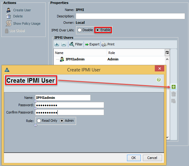
    Servers – Service Profile – Actions – Change Management IP address
  3. Change/Create IPMI user
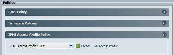
    Servers – Policies – IPMI Access Policies
    IPMI over LAN – Enable
    Create IPMI user. The user name is CaseSENSITIVE!
    Cisco UCS Create IPMI user
  4. Check the policy is associated to the Service Profile or Template
    Policies – IPMI Access Profile Policy – IPMI
    Cisco UCS IPMI Access Profile Policy
  5. Make a note the blade’s CIMC MAC address:
    Equipment – Chassis X – Servers – Server X – Inventory – CIMC – Management Interface
    NB You can hover over the MAC address, Right Click and select Copy
    Cisco UCS CIMC Management Interface MAC
  6. Configure VMware vSphere ESXi host – Configuration – Power Management – Properties
    VMware DPM Edit IPMI iLO Settings
  7. Click OK.
  8. Configure Cluster Power Management:
    Cluster settings – vSphere DRS – Power Management (Manual/Automatic)
  9. You can also put the host in Standby mode manually if required.

EMC Secure Remote Services (ESRS) Policy Manager 6.6 “General System Error”

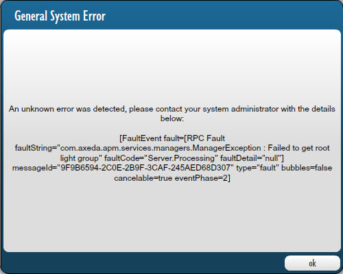
I installed ECM Secure Remote Services (ESRS) Policy Manager 6.6 using default settings. Launching the application page (https://name_or_IP:8443/aps/) failed with General System Error, see screenshot for details.

General System Error:
An unknown error was detected, please contact your system administrator with the details below: FaultEvent fault=[RPC Fault faultString=”com.axeda.apm.services.managers.ManagerException : Failed to get root light group” faultCode=”Server.Processing” faultDetail=”null”]

ESRS Policy Manager General System Error

Apparently, if you install the ESRS Database on the same server as the Policy Manager, all you need to do is to change the Database Port Number from the default port 9001 to, for example, 9002.

ESRS Policy Manager Database Port Number

Hope this will help.

HOW TO: VCE Vblock® Systems Password Change

VCE Vblock consist of many components and when it gets built in the VCE factory, these components are configured with a standard VCE password(s). These passwords can be found in the documentation provided by VCE.  This can be in a form of a spreadsheet or as part of VCE Vblock System As-Built documentation which also includes all technical details for your Vblock (host names, IPs, serial numbers, Site IDs, diagrams etc).

Obviously, it is a security risk to keep standard passwords when Vblock goes into production and therefore it is recommended to get them changes according to your security standards.

If you are not familiar with where and how to change the default passwords, this can be quite time consuming process.  But there is no need to stress about this anymore!  VCE have finally released a document that lists the procedures for changing password on all Vblock components.

The VCE Vblock Systems Password Management document is available on VCE Support Portal under Article Number 3581 / vce3581 (requires VCE Support Portal account).

Enjoy.

PS My Default Passwords page has a good selection of standard passwords for EMC, Cisco and VMware products as well.

HOW TO: Upgrade VMware vSphere Replication Appliance

  • You upgrade the vSphere Replication appliance and any additional vSphere Replication servers by using a downloaded ISO image.
  • The downloadable ISO image is the only means of upgrading from vSphere Replication 5.5.x or 5.6 to vSphere Replication 5.8. You cannot use vSphere Update Manager or the virtual appliance management interface (VAMI) of the vSphere Replication appliance to upgrade vSphere Replication from version 5.5.x or 5.6 to version 5.8.
  • You cannot upgrade vSphere Replication 5.1.x directly to version 5.8. You must upgrade from version 5.1.x to 5.5.x or 5.6 first, and then upgrade from version 5.5.x or 5.6 to 5.8 by using the ISO image for vSphere Replication 5.8.
  • You cannot downgrade to a previous version of vSphere Replication.

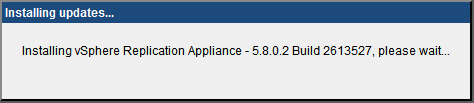
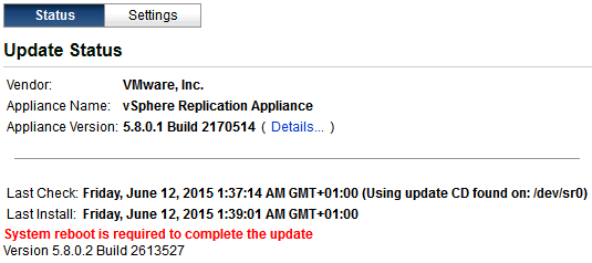
VMware vSphere Replication Appliance documentation:

Upgrade vSphere Replication.  The same procedure is applicable to vSphere Replication Appliance and vSphere Replication Server
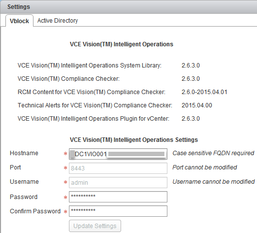
  1. Take vSRA snapshot;
  2. Map the vSRA ISO file to VA’s CDROM drive;
  3. Login to vSRA as root.
    https://<NAME_FQDN_IPADDRESS>:5480/;
  4. Select Update / Settings;
  5. Change Update Repository to Use CDROM Updates
    Click Save Settings;
  6. Click on Update/Status tab
    If previous upgrade got stuck at “Checking for available updates…” and Check Updates button is greyed out even after restarting the vSRA, please refer to “VMware vCloud Connector Server upgrade” article for details.
  7. Click on Check Updates  and confirm the appliance version under Available Updates
    Upgrade_vSphere_Replication_01
  8. Install Updates and OK
    Upgrade_vSphere_Replication_02
  9. After upgrade is complete:
    Upgrade_vSphere_Replication_03
    Restart the appliance, System / Reboot;
  10. Login to vCenter Web Client and check vSRA status:
    vCenter Servers YOURvCenter Manage vSphere Replication

Hope this will help.

VCE Vision vCenter Plug-In upgrade for vCenters in Linked Mode

VCE Vision 2.x has one-to-one relationship with Vblock / vCenter ie if you have two Vblocks / vCenters, you need to install two VCE Vision appliances and link them to the appropriate vCenter.

In my environment I have two Vblocks and their vCenters are configured in Linked Mode for ease of management.

I recently upgraded VCE Vision and the Plug-In for vCenter in one Vblock and noticed that the VCE Vision Plug-In stopped displaying Vblock information in the linked vCenter (although vCenters are in the Linked Mode, you need to use the URL of the second vCenter when you launch vCenter Web Client).

DC1: VCE Vision and the Plug-In for vCenter are v. 2.6.3

VCE Vision IO Plug-In for vCenter - DC1

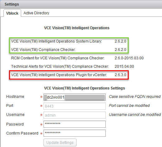
DC2: VCE Vision Plug-In for vCenter is v. 2.6.3 but the appliance is still 2.6.2

VCE Vision IO Plug-In for vCenter - DC2

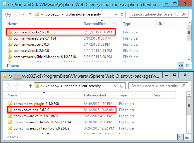
If you have two vCenters in Linked Mode and upgrade VCE Vision appliance and the plug-in for vCenter in one environment, the plug-in will be upgraded on the linked vCenter as well.

Let’s check the VCE Vision Plug-In for vCenter files, by default they are in “C:ProgramDataVMwarevSphere Web Clientvc-packagesvsphere-client-serenity

  • The top screenshot is the vCenter Plug-Ins folder on the first vCenter where plug-in was upgraded from 2.6.2 to 2.6.3. You can see the date and time when the plug-in was upgraded and vCenter Web Client service restarted;
  • On the bottom screenshot we see the plug-in folder on the second (linked) vCenter. As you can see, the plug-in has been upgraded as well.

VCE Vision IO Plug-In for vCenter - DC1 & DC2

I am not sure if it is a bug or a feature, I will forward these findings to VCE Vision development team for analysis.

In the meantime, if you have vCenters in Linked Mode, please upgrade VCE Vision virtual appliances and the Plug-Ins one straight after the other.

PS For the instructions how to upgrade VCE Vision IO virtual appliance and the Plug-IN for vCenter, please refer to “HOW TO: Upgrade VCE Vision” article.


HOW TO: Upgrade EMC PowerPath Virtual Appliance

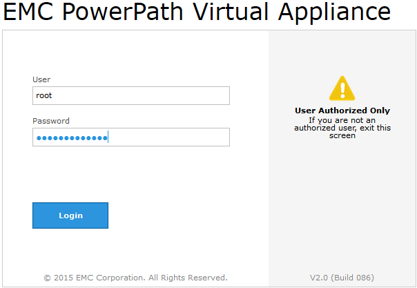
EMC PowerPath Virtual Appliance:

  • is installed separately from the EMC PowerPath/VE for VMware vSphere multipathing product
  • provides a simplified RTOOLS deployment
  • provides enhanced license management
  • provides REST API to retrieve content from PowerPath

EMC PowerPath Virtual Appliance 2.0 has been released:

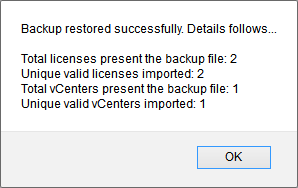
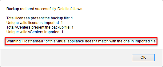
The high-level upgrade procedure is as the following:

  1. Export EMC PP VA 1.2 configuration to a file using the script;
  2. Deploy new EMC PP VA 2.0
  3. Import the configuration file

Here are the detailed steps:
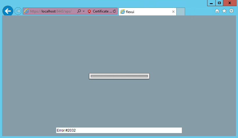
  1. Download PowerPath_Virtual_Appliance_2.0_Package.zip package from EMC Support Portal;
  2. Unzip the export_vApp1.x_Config script from and then copy it to the EMC PowerPath VirtualAppliance 1.2 VM;
  3. SSH into the EMC PowerPath Virtual Appliance 1.2 VM and then run the script to export the EMC PowerPath Virtual Appliance 1.2 configuration.
    login as: root
    Using keyboard-interactive authentication.
    Password:
    Last login: Wed May 13 10:55:02 2015
    epp001:~ # cd /tmp
    epp001:/tmp # chmod +x export_vApp1.x_Config
    epp001:/tmp # ./export_vApp1.x_Config
    [2015-05-13 11:59:01,390] Copying vCenter servers in vcenterserver.xml file.
    
    [2015-05-13 11:59:01,466] Moving vcenterserver.xml file in current folder.
    mv: `/tmp/vcenterserver.xml' and `./vcenterserver.xml' are the same file
    
    [2015-05-13 11:59:01,471] Creating zip archive.
    zip warning: name not matched: /etc/emc/*.lic
    adding: SERVED_142261213XXXX.lic (deflated 25%)
    adding: vcenterserver.xml (deflated 24%)
    adding: deployment_params.properties (deflated 28%)
    
    Virtual Appliance Deployment Parameters
    =======================================
    Host name      : epp001.vstrong.local
    Search Domain  : vstrong.local
    NTP Server     : 10.100.1.1,10.200.1.1
    IP             : 10.100.168.88
    Gateway        : 10.100.168.254
    Subnet mask    : 255.255.255.0
    DNS Server     : 10.100.100.1,10.200.100.1
  4. Copy the resulting vApp1.x_Config.zip file to the local desktop or a remote location.
  5. Take note of the EMC PowerPath Virtual Appliance deployment parameter details.
    The parameters are not copied from EMC PowerPath Virtual Appliance 1.2 for security reasons and therefore requires manual re-entry in EMC PowerPath Virtual Appliance 2.0.

    Virtual Appliance Deployment Parameters
    =======================================
    Host name      : epp001.vstrong.local
    Search Domain  : vstrong.local
    NTP Server     : 10.100.1.1,10.200.1.1
    IP             : 10.100.168.88
    Gateway        : 10.100.168.254
    Subnet mask    : 255.255.255.0
    DNS Server     : 10.100.100.1,10.200.100.1
  6. Power down the EMC PowerPath Virtual Appliance 1.2 VM.
    NOTE: Do not delete the EMC PowerPath Virtual Appliance 1.2 VM until after successful EMC PowerPath Virtual Appliance 2.0 import.
  7. Deploy EMC PowerPath Virtual Appliance 2.0 with the same EMC PowerPath Virtual Appliance Deployment Parameters (see step 5) as EMC PowerPath Virtual Appliance 1.2.
  8. Power up the EMC PowerPath Virtual Appliance 2.0 VM.
  9. Configure EMC PowerPath Virtual Appliance 2.0 VM:
    • Enable VMware Tools
      Run /opt/ADG/etc/init.d/check-vmware-tools
      This script configures VMware Tools and starts it.

      epp001:~ # /opt/ADG/etc/init.d/check-vmware-tools
      Vmware Tools Version - 9.4.0 build-1280544
      Configuring VMware Tools for Linux Kernel - 3.0.101-0.46-default...
      Initializing...
      
      Making sure services for VMware Tools are stopped.
      
      Stopping VMware Tools services in the virtual machine:
      Guest operating system daemon:                                      done
      Unmounting HGFS shares:                                             done
      Guest filesystem driver:                                            done
      
      {skipped}
      
      You can now run VMware Tools by invoking "/usr/bin/vmware-toolbox-cmd" from the command line.
      
      {skipped}
      
      VMware Tools configuration successful.
  10. Open EMC PowerPath Virtual Appliance web console, observe nice new interface and login
    EMC PowerPath Virtual Appliance
  11. In the 2.0 PowerPath Virtual Appliance web console, navigate to System > Settings > Import Backup File and then import the vApp1.x_Config.zip file.
    BTW, you may need to refresh the web console window to be able to click on System
    EMC PowerPath Virtual Appliance - Import the configuration file
    Click OK to confirm you are sure to import the file.
  12. Backup successfully restored
    EMC PowerPath Virtual Appliance - backup restored successfully - 1
    When I re-deployed the EMC PowerPath Virtual Appliance, I changed the host name and therefore I got a warning:
    EMC PowerPath Virtual Appliance - backup restored successfully
  13. Navigate back to PowerPath Licenses and confirm the license assignment
    In one of my environments, the license assignment got lost and all hosts were reported as unlicensed. Navigate to Inventory > VCenter Servers, highlight the vCenter and click on Repoll ESX Hosts button.
  14. After you finish
    • After successful import, EMC PowerPath Virtual Appliance 1.2 can be deleted.
    • Reboot is not required after upgrades using the upgrade script.

Hope this will help.

EMC Secure Remote Services (ESRS) Policy Manager 6.6 Error #2032

When you open EMC Secure Remote Services (ESRS) Policy Manager 6.6 URL “http://localhost:8443/aps“, you are unable to log in and the Policy Manager displays blue/gray screen with the “Error #2032” in the bottom center of the window.
ESRS Policy Manager Error #2032

Policy Manager 6.6 requires that the web client have Flash 11 or above installed. The Policy Manager is complied with dynamic libraries that need to be updated and registered from the Adobe web site. If the customer has the Policy Manager in a locked down network environment that does not have internet access and cannot reach the Adobe Site to update the libraries the Error 2032 is displayed.

To get this fixed, you can either permit Internet Access for the server hosting the Policy Manager or place specific files to the Policy Manager directories.

Please refer to EMC KB Article 000188143 for details.


Cannot open vRealize Automation console after IP address change

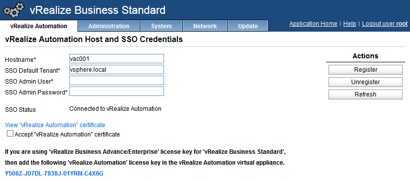
Once you change the IP of the vRealise Automation Appliance you may observe an issue where although you can reach the VCAC splash page i.e. https://<hostname>/ you may not be able to reach the vRealize Automation console i.e. https://<hostname>/vcac

On the VCAC appliance:

Ssh to the appliance and modify the /etc/hosts file to reflect the server’s new IP address:

login as: root
VMware vCloud Automation Center Appliance
root@vac001's password:
vac001:~ # vi /etc/hosts

hosts file content:

 VAMI_EDIT_BEGIN
127.0.0.1 localhost
192.168.100.101 vac001
# VAMI_EDIT_END

Login to vRealize Business appliance management interface, unregister and register with VCAC again:
https://<hostname>:5480

VMware vRealize Business register with vCAC

HOW TO: Configure EMC XtremIO user with Public Key authentication

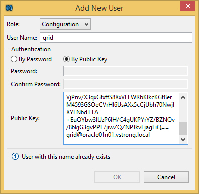
EMC XtremIO array supports two types of authentication for internal users:

  • password
  • public key

In case the user account is used to run scripts and you don’t want to expose the password, using public key authentication would be the preferred method.

In the following example we will configure Linux user to connect to XtremIO:

  1. Login as the user and locate user’s public key:
    login as: grid
    grid@oracle01n01's password:
    grid@oracle01n01:+ASM1:~> cd ~/.ssh
    grid@oracle01n01:+ASM1:~/.ssh> ls -ltr
    total 16
    -rw-r--r-- 1 grid oinstall 420 Apr 24 14:52 id_rsa.pub   <--- Public Key
    -rw------- 1 grid oinstall 1675 Apr 24 14:52 id_rsa
    -rw-r--r-- 1 grid oinstall 840 Apr 24 14:52 authorized_keys
    -rw-r--r-- 1 grid oinstall 2845 Apr 30 10:58 known_hosts
  2. Copy the user’s public key (content of id_rsa.pub file) to the clipboard:
    grid@oracle01n01:+ASM1:~/.ssh> cat id_rsa.pub
    ssh-rsa
    ZZZZZZZZZZZZZZZZEAAAABIwAAAQEAso8m6g2UdJeG+X7PHrYT9UP/QyKpV7f/KquhD4h4/
    nl4oJjBFZU6IztFfZn4F4bMh5e5W7JuM0YeGeMgyZibn6SjSH1ngwFqe1+rO9wptlbkWBHB
    6Byfo+6Im1n20H+dX9kJQ+exCuTmtdUXzDaRtI2TxBJlhEbscEqhErqX7Gb5r067AfXZZZZ
    ZZZZZZZTQiQLDggVLTTVjPnv/X3qxGfxffSZZZZZZZZZZbKIkcKGf8erM4593GSOeCVrHI6
    UsAXx5cCjUbh70NwjlXYFN6dTTA+EuQYbw3IUzP6IH/C4gUKPYrYZ/BZNQv/86kjG3gvPPE
    7jiwZQZNPJkvEjagLiQ== grid@oracle01n01.vstrong.local
  3. Open XtremIO Storage Management Application, Administration, Security, Users Administration, Add
    Select appropriate user role (Administrator, Configuration, Read-Only)
    Select By Public Key and paste the user’s public key into the window.
    EMC XtremIO Add New User Public Key
    Click OK.
  4. Test the user can connect to the storage array
    grid@oracle01n01:+ASM1:/> ssh grid@xio01 "show-volumes"
    Volume-Name Index Vol-Size LB-Size VSG-Space-In-Use Offset Ancestor-Name Index VSG-Index Cluster-Name Index Parent-Folder-Name Index Small-IO-Alerts Unaligned-IO-Alerts VAAI-TP-Alerts Total-Writes Total-Reads Certainty-State
    SRM_PLACEHOLDER 10 2G 512 5.383M 0 10 xio01 1 /CLUSTER06/CLUSTER06-DATA 4 disabled disabled disabled 67.354M 5.451G ok

Hope this will help.

HOW TO: Configure smart zoning on Cisco MDS 9148s

New VSAN is configured in enhanced mode and we’re utilised smart zoning:

Switch01# sh zone status vsan 10
VSAN: 10 default-zone: deny distribute: full Interop: default
    mode: enhanced merge-control: allow           <<---
    session: cli [admin]
    hard-zoning: enabled broadcast: unsupported
    smart-zoning: enabled                         <<---
    rscn-format: fabric-address
Default zone:
    qos: none broadcast: unsupported ronly: unsupported
Full Zoning Database :
    DB size: 532 bytes
    Zonesets:1  Zones:2 Aliases: 4 Attribute-groups: 1
Active Zoning Database :
    DB size: 200 bytes
    Name: zs_vsan10  Zonesets:1  Zones:2
Current Total Zone DB Usage: 732 / 2097152 bytes (0 % used)
Pending (Session) DB size:
    Full DB Copy size: 576 bytes
    Active DB Copy size: 200 bytes
SFC size: 776 / 2097152 bytes (0 % used)
Status:

Implementing configuration changes using enhanced mode means we need to commit changes to the vsan. It’s greatest benefit is to ensure that we can configure a FC network within a single session and locks the fabric.
Smart zoning means that we no longer need to create explicit zones, meaning 1 initiator – 1 target zones. Instead within a smart zone, PWWNs/aliases can all be included within a single zone, however assigned a role (initiator/target), ensuring that there are ACLs still exist.

In the example below we’re going to create a new smart zone per fabric for a new VMware vSphere cluster of hosts, that will connect to the existing EMC XtremIO target ports.

Pre-requisites
  • Have the new device HBA wwpns at hand
  • Have the existing target wwpn aliases at hand
  • Login rights to the MDS switches
  • VSAN IDs where you intend create your new FC Zones
High Level Tasks
  1. Create device aliases
  2. Create FC aliases
  3. Create zones
  4. Add zones to zonesets
  5. Activate zoneset, commit changes & save
Step1 – Create Device Aliases

SwitchA

conf t
device-alias database
device-alias name host01_vhba0 pwwn 20:00:00:25:b5:04:a0:04
device-alias name host02_vhba0 pwwn 20:00:00:25:B5:04:a0:05
exit
device-alias commit

SwitchB

conf t
device-alias database
device-alias name host01_vhba1 pwwn 20:00:00:25:b5:04:b1:04
device-alias name host02_vhba1 pwwn 20:00:00:25:b5:04:b1:05
exit
device-alias commit
Step 2 – Create FC Aliases

Useful for grouping FC hosts

SwitchA (whilst still in configuration mode session)

fcalias name cluster01_hosts vsan 10
member device-alias host01_vhba0 initiator
member device-alias host02_vhba0 initiator
exit
fcalias name cluster01_x10 vsan 10
member device alias X1_SC1_FC1 target
member device alias X1_SC2_FC1 target
exit

SwitchB (whilst still in configuration mode session)

fcalias name cluster01_hosts vsan 11
member device-alias host01_vhba1 initiator
member device-alias host02_vhba1 initiator
exit
fcalias name cluster01_x10 vsan 11
member device-alias X1_SC1_FC2 target
member device-alias X1_SC2_FC2 target
exit
Step 3 – Create zones

SwitchA (whilst still in configuration mode session)

zone name cluster01_x10_hosts vsan 10
member fcalias cluster01_x10
member fcalias hosts_cluster01
exit

SwitchB (whilst still in configuration mode session)

zone name cluster01_x10_hosts vsan 11
member fcalias cluster01_x10
member fcalias cluster01_hosts
exit
Step 4 – Add Zone to ZoneSet

SwitchA (whilst still in configuration mode session)

zoneset name zs_vsan10 vsan 10
member cluster01_x10_hosts
exit

SwitchB (whilst still in configuration mode session)

zoneset name zs_vsan11 vsan 11
member cluster01_x10_hosts
exit
Step 5 – Activate zoneset, commit VSAN changes & save configuration

SwitchA (whilst still in configuration mode session)

zoneset activate name zs_vsan10 vsan 10
zone commit vsan 10
end
copy run start

SwitchB (whilst still in configuration mode session)

zoneset activate name zs_vsan11 vsan 11
zone commit vsan 11
end
copy run start

I hope this will help.